Explaining the different sensor outputs
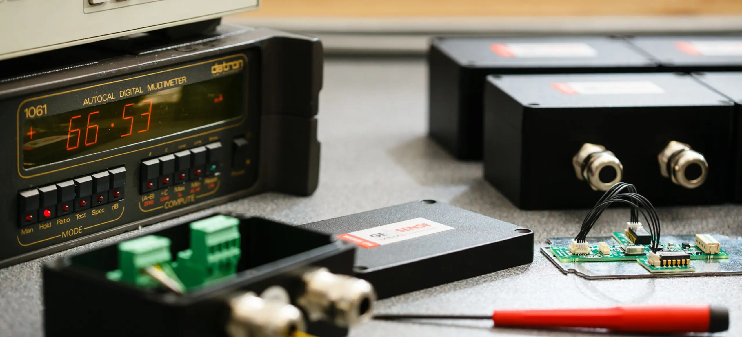
Geosense instruments are fitted with a wide range of sensors with vibrating wire, 4-20mA, Volt, and digital (RS-485) signal outputs.
Each type of signal output is explained together with advantages and disadvantages of each type.
The main advantages of the vibrating wire signal are that very long cables can be used without compromising the accuracy of the measured frequency
FREQUENCY (Vibrating Wire)
A vibrating-wire sensor operates on the principle that a tensioned wire, when plucked, will vibrate at its resonant frequency. Physical changes to the sensor cause a change in the tension of the wire. An electromagnetic “plucking and pickup” coil strums the wire across a specified frequency spectrum. Ideally all frequencies, except for the resonant frequency, will die out in a very short time (20 milliseconds). The wire will continue to vibrate at the resonant frequency for some additional time. As it does so, it will cut the lines of flux in the plucking and pickup coil, inducing a voltage signal with the wire’s resonant frequency, to be fed back to the vibrating wire interface.
Overview
The signal is suitable for use in the world of civil engineering projects. This is because they use the frequency, rather than amplitude, to convey the signal means that vibrating wire sensors are relatively resistant signal degradation from electrical noise, long cable runs, and other changes in cable resistance. This has contributed to their reputation for long term stability and wide usage for monitoring structures such as dams, tunnels, mines, bridges, foundations, piles, unstable slopes, and excavations.
Advantages & disadvantages
The main advantages of the vibrating wire signal are that very long cables can be used without compromising the accuracy of the measured frequency and therefore the calculated Strain, pressure etc. It is also not a problem if the cable is cut and then reconnected with a poor connection that increase the cable resistance as the cable resistance does not impact the frequency of the signal, only the amplitude of it. Because a frequency is transmitted it is also the signal type most immune to induced noise from Electromagnetic and RF sources.
Historically VW sensors were not suited for dynamic monitoring but with advances made by Campbell Scientific with their VWIRE 305 this is now possible and Geosense sensors have been tested and used on several projects.
4-20mA current output is good if it has to travel through medium length cables before being processed
4-20mA
Sensors having a 4-20mA output are calibrated over this range against various engineering units such as so that the output value corresponds to a specific value of pressure, temperature, load, tilt etc.
However this output value must be compared to the individual calibration certificate for each sensor and a mathematical manipulation made (see data handling for individual sensors) to obtain the absolute value.
The loop’s operation is straightforward: A sensor’s output signal is first converted to a proportional current, with 4mA normally representing the sensor’s zero-level output and 20mA representing the sensor’s full-scale output.
Overview
Current is rate at which charge is moving. It is measured in amps (A) or milliamps (mA), which is the change in charge over the change in time (dq/dt).
As far as electronics, the current signal is the measure of the current in the circuit (what is a circuit)
The 4-20 mA current loop is a very robust sensor signalling standard. Current loops are ideal for data transmission because of their inherent insensitivity to electrical noise. In a 4-20 mA current loop, all the signalling current flows through all components; the same current flows even if the wire terminations are less than perfect. All the components in the loop drop voltage due to the signalling current flowing through them. The signalling current is not affected by these voltage drops as long as the power supply voltage is greater than the sum of the voltage drops around the loop at the maximum signalling current of 20 mA.
Why is 4mA chosen as the lower threshold representing the ‘off’ or ‘closed’ position?
The design takes into account that there must be a means of representing a fault caused by an open circuit or a lost feed. Therefore, a reading of 0mA is essentially “reserved” to signal a fault in the system, while a reading of approximately 4mA or 20mA would indicate a properly working circuit.
Advantages & disadvantages
Current output is good if it has to travel through medium length cables before being processed. Sending a signal over longer distances produces voltage losses in the system however the magnitude of the current in the loop is not affected by voltage drops in the system wiring since all of the current (i.e. electrons), originating at the negative (-) terminal of the loop power supply has to return back to its positive (+) terminal.
The other advantage of using a current loop over voltage is a current loop’s inherent insensitivity to electrical noise. Its main advantage over digital and VW is its suitability for dynamic monitoring.
Transmitting a sensor’s output as a voltage over long distances has several drawbacks
VOLTAGE
Sensors can have various Voltage outputs 5 volts, 10 volts -5 to +5 volts and more. Sensors having a Voltage output are calibrated over this range against various engineering units such as so that the output value corresponds to a specific value of pressure, temperature, load, tilt etc.
This output value must be compared to the individual calibration certificate for each sensor and a mathematical manipulation made (see data handling for individual sensors) to obtain the absolute value. There are two types of Voltage signal, Differential and Single-ended Measurements.
A differential voltage is “floating”, meaning that it has no reference to ground. The measurement is taken as the voltage difference between the two wires. The main benefit of a differential measurement is noise rejection because the noise is added to both wires and can then be filtered out by the common mode rejection of the data acquisition system. Differential measurements should be used if the sensor is in a noisy environment or for sensors with output voltages susceptible to noise interference.
A single-ended measurement is taken as the voltage difference between a wire and ground. The noise is only on the positive wire and as a result, it is still measured along with the output voltage from the sensor. A sensor with a differential output can be wired for single-ended by wiring the low side to ground. This is usually done to reduce the number of channels needed to measure the sensors.
It should also be noted that taking a single-ended vs. differential measurement might also be based on the data acquisition system or the cabling. Shielded twisted-pair cable is also very effective at reducing noise in the signal other types of cable might not have the same effect.
Overview
Voltage is the measure of the amount of work it takes to move a charge from one point to another, usually across a potential difference. Voltage is measure in volts (V), which is 1 joule per 1 Coulomb (1 J/C). If the resistance of a lead wire changes due to the length being increased/decreased or even temperature change then the work taken to get from one end of the cable to the other is altered. Every connection in a system also creates resistance changes which will again alter the voltage reading. While using differential signalling helps, this does not eradicate the issue. Voltage signals are thus best used for short cable lengths in environments where Electromagnetic and RF noise is at a minimum.
Advantages & disadvantages
Transmitting a sensor’s output as a voltage over long distances has several drawbacks. Transmitting voltages over long distances produces correspondingly lower voltages at the receiving end due to wiring and interconnecting resistances. Voltage devices are also sensitive to noise pickup. Shielded wires can be used to minimise noise pickup, but their high cost may be prohibitive when long distances are involved.
The advantages of an RS-485 signal are reduced logging cost due to decrease of logging channels required
DIGITAL
Many sensors now use a digital signal rather than the analogue signals of voltage or current. Like voltage there are single ended and differential types of signal. The two most common being RS-232 and RS-485 we do not use RS-232 sensors due to the short cable lengths and the propensity to be effected by Electrical noise. We instead use sensors employing RS-485 communication.
RS-485 is a standard defining the electrical characteristics of drivers and receivers for use in balanced digital multipoint systems. Digital communications networks implementing this can be used effectively over long distances and in electrically noisy environments.
Overview of RS-485
RS-485 only specifies electrical characteristics of the generator and the receiver. It does not specify or recommend any communications protocol, only the physical layer. Modbus, Profibus, Canbus and SDI 12 are all examples of communication protocols employing the RS-485 style signal.
The major advantage of the RS-485 system is that sensors can be bussed, meaning that each sensor has its own individual address and many can be all attached on to one cable. This means that multiple sensors only use up one port on the data logger saving considerably on cable and data logging costs. Long distances are achievable but the distance is a function of the cable and supply voltage. The longer the cable the greater the signal attenuation will be and so the length is not infinite. Signal attenuation also increases with frequency of data transfer and the achievable distance also diminishes with data rate.
Advantages & disadvantages
The advantages of an RS-485 signal are reduced logging cost due to decrease of logging channels required. The cost and ease of installation is also reduced as only one cable has to be run per network path and an individual cable to each instrument is not required. The signal of the sensors, though not immune, is also significantly less affected by EMI and RF noise than Current and Voltage signals. Digital signals are not suitable for dynamic monitoring due to the delay in signal conversion from analogue to digital and also the time for polling the sensor for readings.