Introduction to Vibrating Wire Piezometers
Overview
Rugged proven technology
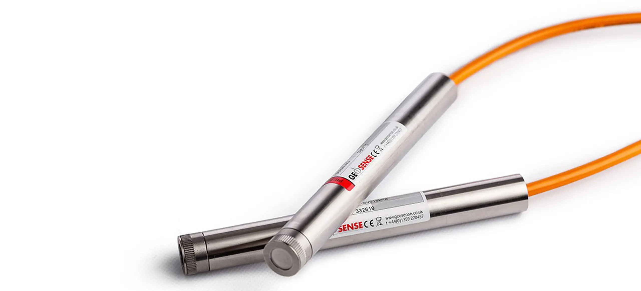
Vibrating wire piezometers are designed to measure water pressure and are well known for their reliable long-term performance and suitability for demanding environments which usually exist in civil engineering projects.
Long term performance
Vibrating wire piezometers have a proven record of long-term stability over decades, with no drift from the original zero.
Long cable lengths
In addition to the above, signals are capable of long transmission distances (~ 2km) without degradation. They are also somewhat tolerant of damp wiring conditions and resistant to interference from external electrical noise.
Lightning protection
All Geosense piezometers are fitted with 90V gas plasma arrester as a safeguard against lightening.
Temperature sensor
All Geosense piezometers have internal thermistors to measure temperature.

SELECTION
Type
- Standard – for direct burial in fills, embankments and boreholes
- Heavy duty – robust body to resist high point loads
- Low pressure – for shallow groundwater applications
- Vented – to compensate for barometric pressure changes
- Drive-in – shallow installation in soft or loose (4-10 kPa) soils
Range
The range will depend on the expected water pressure as per the table below.
| M (Water) | Bar | Kpa | Kips | PSI |
| 17.5 | 1.72 | 172 | 0.03 | 25 |
| 35 | 3.45 | 345 | 0.05 | 50 |
| 52.5 | 5.17 | 517 | 0.08 | 75 |
| 70 | 6.89 | 689 | 0.10 | 100 |
| 105 | 10.34 | 1034 | 0.15 | 150 |
| 210 | 20.69 | 2068 | 0.30 | 300 |
| 350 | 34.47 | 3447 | 0.50 | 500 |
| 525 | 51.71 | 5171 | 0.75 | 750 |
| 700 | 68.95 | 6895 | 1.00 | 1000 |
| 1050 | 103.42 | 10342 | 1.50 | 1500 |
| 1400 | 137.89 | 13789 | 2.00 | 2000 |
| 2100 | 206.84 | 20684 | 3.00 | 3000 |
| 3500 | 344.74 | 34474 | 4.00 | 5000 |
Filter
There are two types of filters:
- LAE (Low Resistance to Air Re-Entry) – typically used for most applications including the Fully Grouted Method
- HAE (High Resistance to Air Re-Entry) – typically installed in fill which starts as unsaturated but then becomes saturated such as in an earth fill dam or where negative pore water pressures are anticipated. All HAE filter tips should be fully saturated prior to installation.
ALL GEOSENSE VW PIEZOMETERS FITTED WITH HAE FILTERS ARE PRE-SATURATED IN THE FACTORY & PLACED IN A SEALED TUBE TO ELIMINATE THE NEED TO SATURATE ON SITE, AND ALL THE PROBLEMS ASSOCIATED WITH THIS
Calibration
All piezometers are calibrated against known pressures
Negative Calibration
Negative calibration of a Geosense piezometer is possible and the maximum is -70kPa.
Cable
Cable lengths will need to be adjusted to accommodate being terminated at a logging point or manual reading point. It is recommended to allow an extra 3-5 metres on top of the borehole depth and distance to the termination.

INSTALLATION
Multipoint installation
Several piezometers can be installed in a borehole in two different ways:
- Multiple piezometers installed at different levels with individual cables. Installation is often carried out by attaching the piezometers and cables to a central access tube which allows accurate installation depth and the central tube can be used for Tremie grouting of the borehole.
- Multipoint piezometer strings are several piezometers but with only one cable making installation simpler than the above method. This is typically used in the fully grouted method (see below).
Site Zero Pressure reading
VW Piezometers differ from any other sensor in that they indicate a reading at ZERO pressure. This value should be checked before installation and should be within 50 digits of the calibration certificate. Any larger changes could be a result of temperature or damage during transportation. See manual for full details on how to take Site ZERO pressure readings.
NOT TAKING A SITE ZERO PRESSURE READING WHEN INSTALLING IS THE MOST COMMON ERROR MADE. DON’T MAKE THIS ERROR!
Base/initial reading
Whilst everything will be referred back to the Site Zero pressure reading, this is the starting/reference point once the piezometer has been installed and any change in subsequent readings will demonstrate a change in the installation.
Response zone
The conventional installation method requires the piezometer to be surrounded by a sand intake zone and then sealed with a Bentonite seal and is known as the response zone.
Grouting
Traditional grouting is normally used to fill the borehole above a Bentonite seal and is typically a 2:1 cement/Bentonite mix and placed by Tremie.
- Fully grouted method is a faster and easier way to install piezometers and is gaining in popularity within the industry. It eliminates the conventional sand filter and the bentonite seal. Instead, the entire borehole is filled with a non-shrinking, low permeability grout.
See other Blogs for grout specifications.
OPERATION
Readings
Readings can be collected from the instrument either through a portable readout or a logger. You can find more information in the readout/loggers’ section, however a quick instruction is provided below for the VWR-1 readout.
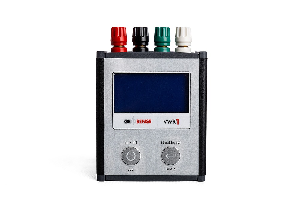
Connect signal cable from the sensor to the readout following the wiring colour code. Conductor colours may vary depending upon the extension cable used. Commonly these are:
| RED | VW+ |
| BLACK | VW- |
| GREEN | TEMP |
| WHITE | TEMP |
Switch on the unit
The readout displays the Vibrating Wire reading (in Hz2/1000 – Linear Digits) and a temperature reading in resistance and °C.
Sweep Range is the frequency range over which VW piezometers operate and is 2200 – 3500 Hz. The appropriate sweep range should be selected on any readout.
Barometric pressure – In some locations, barometric variations are small except when there are storms. In other locations, normal weather may bring barometric pressure changes as large as 34 mb (0.5 psi) during a day, and 68 mb (1 psi) during a year.
To eliminate the measurement uncertainty introduced by changes in barometric pressure, a correction can be applied
If the transducer is measuring the water level in a standpipe or well that is open to atmosphere, the pressure measured by the piezometer is the combined pressure of water and the air above the surface of the water. If the barometric pressure drops, the piezometer will return a decreased pressure, even if the water level remains unchanged. To eliminate the measurement uncertainty introduced by changes in barometric pressure, a correction can be applied. Either a special barometric transducer or an additional low pressure piezometer can be used to measure atmospheric pressure.
Barometric Pressure Correction
The following is an example of how to carry out the correction using data from a special barometric transducer or other weather station information:
Where a low pressure piezometer is used to measure the barometric pressure, the atmospheric pressure data can be recorded in the same units as the other piezometers, making compensation a simple addition of the difference (positive or negative).
Obtain barometric pressure readings on site at the time of reading the piezometer. Ideally the barometer should provide the actual pressure of the atmosphere at the location of the monitoring site. Off-site reports from weather stations can also be adequate for this purpose since it is only the relative change in pressure.
Atmospheric Pressure when Zero recorded (mbar): 1022
The same source of pressure that was noted when the piezometer zero values recorded must be used for all subsequent readings.
Site Zero Pressure Reading in Linear Digits (B units): 9555.5
Current Reading in Linear Digits (B units): 9244.3
Current Atmospheric Pressure (mbar): 1007
Calculated water pressure in mH2O
Calculated water pressure in mH2O (m) 5.651
Subtract the barometer reading obtained when the site zero value was recorded, from current barometer reading in mbar. This is the barometric pressure correction value.
Change in Atmospheric Pressure (mbar) = 1007-1022
= -15mb
Convert the barometric correction value to the engineering units being used for the piezometer data, by multiplying it by the applicable factor
(for example:- 0.1 for kPa, 0.014504 for psi or 0.0101972 for m H2O)
Convert mbar change to mH2O = 15 x 0.0101972
= -0.153m H2O
Minus the barometric correction, in engineering units, to the pressure reading:
Compensate for pressure change = (5.651 – (-0.153))
= 5.498m H2O
Temperature
Where a piezometer is installed in a zone where its temperature is likely to fluctuate significantly, records of both pressure and temperature data should be recorded. They can then be used to assess any temperature effects on the pressure readings.
Where the piezometer is sealed in a borehole or buried in fill, there is usually little variation in temperature, so temperature effects will be small and corrections will not be necessary. However, if a low range piezometer is suspended in a shallow standpipe or well, it may be affected by day to day changes and seasonal changes in temperature. In this instance, temperature corrections could become more important. Thermal influences on Piezometer readings are complex. Therefore, in order to correct for temperature it is first necessary to establish the effects of temperature changes on a particular piezometer and the medium in which it is installed. (It must be remembered that the density of water also changes with temperature). To establish the true effects of temperature changes, it is necessary to accurately verify the head acting on a particular piezometer using an alternative means. It is necessary to record both the water pressure from the piezometer, the piezometer temperature and the true water depth over the piezometer diaphragm. Over a full annual cycle, both the seasonal and daily thermal affects can be computed from these data. Corrections would be carried out using a similar principle as for Barometric Pressure.
ALL GEOSENSE VW PIEZOMETERS ARE TEMPERATURE AND PRESSURE CALIBRATED
TROUBLESHOOTING
Unexpected Data
It is generally accepted that when a vibrating wire instrument is producing a stable reading on a suitable readout, the value will be correct. In almost all cases, a fluctuating reading is a sign of a faulty signal from the sensor. The fault could be in either the sensor, the connecting cable, any switch boxes or the readout. The best way to find a fault an instrument is to isolate it from all other instruments and connections. Where possible begin fault finding from the sensor itself.
Troubleshooting of VW sensors can easily be carried out by resistance testing of individual conductors. See Blog Troubleshooting Vibrating Wire Instruments.